
21. How is the reflectivity gradient important to severe weather? The reflectivity gradient is defined as how much the value of radar reflectivity changes over distance. If the reflectivity changes significantly over a small distance then that would be a strong reflectivity gradient. If the reflectivity changes only slightly over a significant distance then that would be a weak reflectivity gradient. Determining what is a strong gradient, weak gradient or a gradient that is in-between takes practice. With a few examples we will show how each look on radar. First we will look at a commonly used scale for reflectivity values. The scale is shown below:  The green colors represent light reflectivity (light rain aloft), the yellow colors are more of a moderate reflectivity (moderate rain aloft) and the red colors represent heavy reflectivity (heavy rain and possible hail aloft). An example of a strong reflectivity gradient is a red color next to no reflectivity while an example of weak reflectivity would be a gradual transition from green to yellow colors. Below is an example of a weak, moderate and strong reflectivity gradient. WEAK REFLECTIVITY GRADIENT 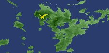 MODERATE REFLECTIVITY GRADIENT 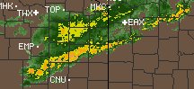 STRONG REFLECTIVITY GRADIENT 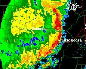 The reflectivity gradient is important because it can give clues to if severe convective wind gusts are occurring. Severe convective wind gusts are more likely to occur when there is a strong reflectivity gradient. The leading edge of severe thunderstorms often have an abrupt transition zone of heavy precipitation and wind. In this region the outflow from the storm is progressing into the environmental air ahead of the storm. Strong convective winds will force the reflectivity into an abrupt zone where the reflectivity changes rapidly over a small distance. Look for severe convective wind gusts when red reflectivity is next to very little or no reflectivity. This is especially true if the storms are in a line segment that is bowing. 22. What are echo tops and their importance? An echo top is the radar indicated top of an area of precipitation. Once the precipitation intensity drops below a threshold value as the radar beam samples higher elevations of a storm or precipitation region then the echo top is located. The cloud top will often extend above the echo top since clouds are more difficult to detect by radar. Echo tops can be used to assess the intensity of a storm. The rule of thumb is that the higher the echo tops are in a storm then the stronger the updraft is that produced that storm. A stronger updraft makes convective wind gusts and large hail more likely. When there are several storms on radar, the ones with the higher echo tops may be the most likely ones to produce the most significant severe weather (convective wind gusts and hail). 23. What is bright banding and how does it occur? Bright banding occurs due to the higher reflectivities associated with snow that is melting as it is falling aloft. Ice is a better absorber of radar radiation compared to liquid water. Because of this, snow will show a lower reflectivity on radar when it has the same moisture content as a rain event. When the snow is melting however, a film of water forms on the outside of the snowflake. Since snowflakes can be fairly large, when there is a film of water on the snowflake it has the same reflectivity as a a giant raindrop or small wet hail. A radar beam will generally sample a higher elevation as it moves away from the radar site. Because the melting of the snowflakes occurs within a specific elevation range aloft, there will be a higher reflectivity as the radar beam moves through this layer. This can produce a circular or arcing band of higher reflectivity around the radar site on the reflectivity display. Below are some bright banding examples (more examples will be added over time): Dallas / Ft. Worth Area Bright Band 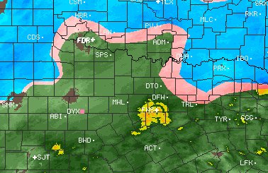
24. VIL and updraft strength? VIL (Vertically Integrated Liquid) is a summation of reflectivity through a vertical column of the troposphere. VIL is most accurate at the medium ranges from the radar site since the radar is able to sample most of the vertical column of the storm. If the storm is too close to the radar then part of the storm will be in the cone of silence and if the storm is too far from the radar then the bottom portion of the storm under the lowest tilt angle will not be sampled. The higher an updraft penetrates through the troposphere then it is more likely significant moisture has been funneled and suspended in that vertical column. If it is not apparent on reflectivity which storms have the strongest updrafts then the VIL can be used to determine which storms are most likely to have the strongest updrafts. Higher VIL values occur with suspended hail, heavy rain and precipitation extending through a deep vertical depth of the troposphere. 25. How does snow look on radar? Snow often has the following features on radar: a. A fairly low reflectivity for dry snow. Wet snow can have a much more significant reflectivity. Determine the likely water content of the snow along with examining the radar images. b. The gradient between colors tends to be gradual. Often there are varying shades of the lower reflectivity colors. c. It tends to have a grainy or fuzzy appearance. The edges of the precipitation areas may not have a well defined edge in light snow situations. Below are some examples of snow on radar (more examples will be added over time): SNOW ON RADAR 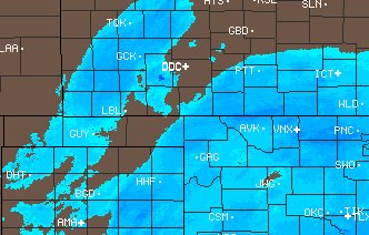
26. What creates a bow echo? Bow echoes, when they occur, usually occur with a grouping of multicell storms that are arranged into a squall line. The upper tropospheric winds steer storms. These winds help determine the speed and direction that the storms move. The upper tropospheric winds will not always be constant along a squall line. In the regions these winds are stronger that portion of the squall line will surge forward. Also, in regions these winds are drier that portion of the squall line will surge forward because evaporative cooling creates negative buoyancy that will further accelerate a downdraft toward the surface. Since the downdraft from a squall line approaches the earth's surface at an angle, the faster the downdraft winds the faster the storms may migrate forward. Below is an example of a bow echo: BOW ECHO  The next example is that of a bow echo with a line-end vortex on the north side of the squall line: LINE-END VORTEX 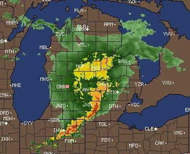
27. What is an inflow notch? There are two types of inflow notches that will be discussed which are the low level inflow notch into the updraft of a storm and the mid-level rear inflow notch into the back side of a storm. The characteristic that both types of inflow notches have is that there tends to be reduced reflectivity in the region they occur since the air is either too dry or is moving too quickly to allow precipitation to develop or fall through this air. First will be shown a couple of examples of inflow notches into a supercell. Within the inflow region is the updraft. There tends to be lower reflectivities in the updraft region and higher reflectivities in the downdraft region. Within an inflow notch is the low level wind into the updraft of the storm. A classic supercell will take on a hook like feature and an HP supercell will take on a kidney bean feature. An example of each is shown below: Classic Supercell 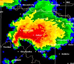 HP Supercell 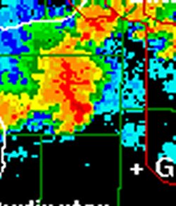 A rear inflow notch enters the backside of a storm in the middle levels of the troposphere. These inflow notches are particularly conducive to severe weather if they ingest high momentum and dry air into the storm. If the air is dry it will cool through evaporative cooling. This will increase the negative buoyancy of the air and it will accelerate toward the earth's surface. This negative buoyancy acceleration along with the air's initial high momentum can produce severe convective wind gusts at the leading edge of the storm or storm complex. An example of a storm complex with a rear inflow notch is shown below: 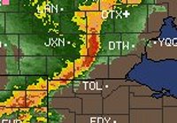
28. Anvil blowoff on radar Much of the light precipitation detected on radar does not reach the ground. This is especially true if there is a dry layer of air between the surface and from where the precipitation is falling. This is even more especially true if the precipitation falls through a deep dry layer and the precipitation begins the fall from high aloft. Rain falling from high aloft is very common in the downwind portion of a thunderstorm. Mammatus and virga are common on the downwind side of a storm. When the radar beam gets high enough it will detect these thick clouds and virga aloft. This may mislead the radar operator into thinking precipitation is reaching the ground in those locations when it is not. Strong winds will shear the top of a thunderstorm. This moves thick cloud, precipitation and virga downwind from the storm. If this shows on radar as a green color it is likely not reaching the ground. Keep the following in mind: 1. Anvil blowoff will be especially evident at long ranges from the radar since the radar beam increases in elevation away from the radar site. 2. Anvil blowoff will generally show as light reflectivity (usually color coded green) and this reflectivity generally does not result in precipitation reaching the ground. 3. Strong updrafts in a strong shear environment (strong upper level wind) will often have the anvil blowoff showing on radar. 4. Anvil blowoff tends to show up best on composite reflectivity since it is using multiple tilt angles and showing reflectivity from all the different angles. Here are some example of anvil blowoff from storm(s) on radar: 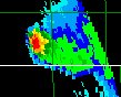 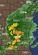 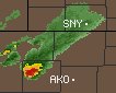 29. Recognizing flooding potential on radar Radar is an important nowcasting tool for recognizing flooding potential. Flooding occurs when too much rain falls over a given time period for the ground surface to support. The flooding potential will be greater when storms move over previously saturated land, snowmelt combines with rainfall or rain falls over land that has a low permeability. Any of the following seen on radar can produce flash flooding especially if the land is already saturated: 1. Training thunderstorms- thunderstorms developing and moving over the same areas that previously had thunderstorms. 2. Very intense slow moving thunderstorms- a single slow moving thunderstorm can produce several inches of rainfall per hour. 3. Consistent rain- rain (especially heavy rain) falling over an extended period of time. 30. Calculation of radar shear There are many different types of shear. When it comes to the use of the term shear on a Doppler radar product what is usually being referred to is the addition and inbound and outbound winds that are adjacent to each other. For example, if a radar meteorologist says there are 80 knots of shear it means the winds going toward the radar added to the winds going away from the radar on two adjacent radar range gates is 80 knots. Another term that is used in radar meteorology is the rotational velocity. This is found by adding the inbound and outbound winds and dividing by 2. If the inbound velocity is 30 knots and the outbound velocity is 52 knots, then the rotational velocity will be 41 knots. 31. Inversions and radar ground clutter The temperature profile of the troposphere makes a strong contribution to how radar emitted radiation will refract in the troposphere. Superrefraction is the beam bending more toward the earth's surface than in normal tropospheric conditions and subrefraction is the beam bending less toward the earth's surface than in normal tropospheric conditions. An inversion is a situation in which the temperature increases with height. Thus it is a situation where there is colder air under warmer air. An inversion layer is a layer of stability since cold air under warm air is a stable situation. A common type of inversion is the radiational cooling inversion in which overnight the earth's air near the surface cools by ground surface longwave radiation emission. The optimum conditions for a radiation inversion is a dry, clear and long night. Inversions at and near the earth's surface can also occur due to shallow cold front passages and evaporative cooling in the boundary layer. An inversion promotes superrefraction. Ground clutter is returns to the radar from radar emitted energy scattering off of objects on and near the earth's surface. Ground clutter is most evident when low tilt angles are used since the radar energy travels close to the earth's surface especially at close ranges to the radar. Since a superrefraction situation causes the radar beam to travel closer to the earth's surface, superrefraction will promote an increase in ground clutter. Thus, the combination of a low tilt angle and an inversion at and near the earth's surface promotes an abundance of ground clutter. Below is an example radar images using the lowest tilt angle (0.5 degrees) taken in the morning when a radiation inversion was in place. 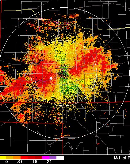
32. Rmax and Vmax as it relates to the Pulse Repetition Frequency The Pulse Repetition Frequency (PRF) is the number of radiation pulses emitted by radar in 1 second. For example, if the radar emits 400 pulses in one second then the PRF is 400 pulses/second. Think of pulses like the pulses of a strobe light. A strobe light alternates between light and dark and there is light a certain number of times within a given period of time. Radar is similar except the number of pulses is much more per second than a strobe light and radar emits microwave type wavelength radiation. Another difference is that the radar spends less than 1% of the time emitting radiation and over 99% of the time sensing for returned radiation. Radar can sample the troposphere very fast because the speed of light is fast (about 300,000,000 meters per second). Rmax stands for the maximum range the radar can detect. If the radar emitted a pulse of energy and waited as long as needed for returning radiation then the radar could detect to any range. However, since the speed of light is so fast compared to the distances we need to measure returns in the troposphere the radar is not required to wait more than a tiny fraction of a second for return energy to come back. Thus, the radar can be set to emit and listen for 100s of pulses per second and we can still measure ranges that cover a broad area. However, the faster the PRF becomes the smaller of a range that can be detected. If the PRF is set too fast then there is not as much time to sample the troposphere in one pulse before the next pulse is sent out. Energy returned from one pulse after another pulse has been sent will be range folded. Suppose the PRF is 500 pulses per second. The formula for Rmax is C / (2 * PRF). C stands for the speed of light. With a PRF of 500 pulses/s, the Rmax is = 300,000,000 m/s / (1,000 s^-1) = 300,000 m which is equal to 300 km. Thus the radar can sample up to 300 km during each pulse. If a return is beyond 300 km then it will be range folded and will show up at a distance closer to the radar than the return really is because the radar thinks it is getting returns from a second pulse it already sent out. Suppose we increase the PRF to 1,200 pulses per second. Rmax then becomes 300,000,000 m/s / (2,400 s^-1) = 125 km. From these two examples you can see that as the PRF increases, then the Rmax becomes a smaller range. This makes sense because the faster pulses are emitted the less time there is for the pulse to travel and come back to the radar before the next pulse is emitted. If we want to detect echoes beyond 125 km we will need to decrease the PRF from 1,200 to a smaller number. When a reflectivity image is put into motion we can see where the precipitation areas are moving toward and how fast they are moving. However, we can not see the motions within the precipitation areas very well. To help with that problem Doppler radar has come along. Vmax stands for the maximum velocity the radar can detect. Precipitation particles that are sensed are either moving closer to the radar over time, further from the radar over time or stay the same distance from the radar over time. It is this motion we want to detect because from it the motions inside rain clouds can be sensed. The motion of precipitation particles or other particles is determined by the phase shift that occurs from radar radiation striking the particle. Suppose you throw a ball at a wall that is moving at you and then throw another ball at the same velocity at a wall that is moving away from you. The ball you threw at the wall that is moving toward you will rebound faster off the wall back toward you. Thus, the velocity of the ball changes relative to you depending on if the wall is moving further or closer to you even if you throw it at the same velocity toward the wall both times. This principle does not work with light because the speed of light is a constant. However, the frequency (number of light waves passing a point over time) and wavelength (distance from beginning to end of each wave) does change. It is from the phase shift of light that is used by radar to determine whether an object is moving toward or away from the radar and the magnitude of that motion. Suppose the PRF is 500 pulses per second using a 0.1 meter wavelength radar. The formula for Vmax = (PRF * wavelength) / 4. With a PRF of 500 pulses/s, the Vmax is = (500 s^-1 * 0.1 m) / 4 = 12.5 m/s. Thus the radar can only sample motions that are equal to or less than 12.5 m/s. If the actual velocity of an object is 17.5 m/s that echo will be velocity folded and will have a value of (17.5 - 12.5 = 5 m/s). If we want to detect higher velocities without them being folded the PRF needs to be increased. Suppose we increase the PRF to 1,200 pulses per second. Vmax becomes (1,200 s^-1 * 0.1 m) / 4 = 30 m/s. From these two examples you can see that as the PRF increases, then the Vmax becomes higher. Think of a strobe light once again and the strobe light shining on a bouncing ball. If the strobe light flickers more quickly (higher PRF) and we watch it in slow motion then we can predict where the ball will be each time the light shines on it again. However, if the pulses are longer (PRF decreased) to the point where the light shines again slower than the time it takes the ball to make one bounce we will not know whether the ball is rising or falling (it has folded and we can no longer be sure where it will be when the light shines on the ball on the next pulse). The phase shift of light is smaller the higher the PRF is. As the PRF decreases the phase shift becomes more. Once the phase shift becomes too much then the velocity will be folded. 33. Recognizing veering and backing wind on radial velocity Please read the following Haby Hint: http://www.theweatherprediction.com/habyhints/48/ On radial velocity, red and yellow colors represent motion away from the radar and greens and blues represent motion toward the radar. As the radar beam moves away from the radar site it will usually increase in altitude as range from the radar increases. Thus, locations near the radar site will be sampled close to the surface while locations at the outer range of the radar will be sampled at a much higher elevation. Radial velocity colors will only be shown where there is hydrometeors or other particles in the troposphere for the radar beam to scatter off. It is precipitation and thunderstorm areas where the best returns will occur. The images below are idealized since they show colors across the entire radar sampling area. This is reality would generally only occur if precipitation was occurring across the entire radar sampling region. Look at the image below depicting an idealized veering wind. The winds near the radar are from the east. We know this because of the yellow colors immediately to the west of the radar (motion away) and the blue colors immediately to the east of the radar (motion toward). The white curving line on the image is the zero radial motion. Within the area in white motion is neither toward or away from the radar but is rather motion that is remaining equidistant from the radar site at that point in space. A key point to remember is that the winds will flow perpendicular to this white zero radial velocity line. At the middle ranges from the radar site the winds are from the southeast and south. We know this is the wind direction here because winds cross the white radial velocity perpendicularly and motion is from the blue and green colors toward the yellow and red colors. At the outer ranges of the radar the wind is from the southwest. The outer ranges of the radar will be the highest in elevation sampled. Thus, going from the surface to aloft the winds shift from easterly to southeasterly to southerly to southwesterly. This is a veering wind since the wind is turning clockwise with height. A veering wind is associated with warm air advection since low level winds from a southerly direction will generally transport in warmer air. Remember the initials CVW, where these letters stand for Clockwise, Veering, Warm Air Advection. A veering pattern on radial velocity will have an S-shaped pattern. See the veering wind image below and notice the S-shaped signature made by the white zero radial velocity radial. A student posted a message for the way to remember that an S-shaped pattern is associated with warm air advection is to remember that Superman has a warm heart. Superman has an S on the shirt. The second image below shows a backing wind. The wind is from the east at the surface, then gradually shifts to the northeast and then to the north at the outer range. A backing wind will shift counterclockwise with height. Remember the initials CCBC, where these letters stand for Counter-Clockwise, Backing, Cold Air Advection. A backing wind pattern will have a backward-S shaped radial velocity pattern. VEERING WIND WITH HEIGHT 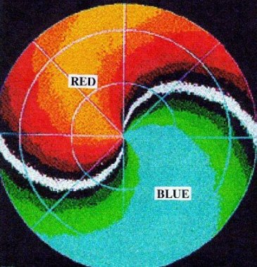 BACKING WIND WITH HEIGHT 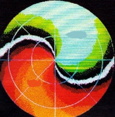
34. Wavelength and frequency of light and perspective of observation In a vacuum light travels at the maximum velocity which is 299,792,458 m/s. Light will travel slower than this speed and will decelerate when it travels through gases (such as the earth's atmosphere), liquids (such as the earth's ocean) and land. The denser the object and the longer light has to travel through the object, the more light will slow down and absorb into the object. If the substance is dense enough such as land or very deep waters it will absorb the energy completely. Light has a couple of important properties which are frequency and wavelength. Light travels as both a particle and a wave. Waves have a frequency (number of waves passing a fixed point through time) and a wavelength (length of one complete wave). The frequency is measured in Hertz (waves passing per second) and the wavelength is measured in meters or fractions of a meter. While the maximum speed that light travels is not a function of relativity, the motion of an object compared to the motion of surrounding objects will cause the wavelength and frequency to be different from different perspectives. Suppose an object emits radiation with a wavelength of 7 micrometers and this object is moving quickly away from an observer. The observer will discover the wavelength as being greater than 7 micrometers when it reaches the observer. This is called a red shift since the wavelength is observed as being longer than what the emitter radiates. The light from many galaxies is red shifted and this is used as evidence that the universe is expanding since many galaxies are moving away from each other. Imagine a very long rope with waves traveling through the rope. Suppose you are stationary and notice 100 waves passing you per minutes. Now suppose you are set in motion in the same direction the waves are moving through the rope. From this new observational perspective you will notice less than 100 waves passing you per minute. The frequency has decreased. This is a red shift. When the frequency of light decreases the wavelength increases. When an emitter of radiation is getting closer to the observer over time the observer will notice a higher frequency and shorter wavelength than what the emitter is radiating. This is known as a blue shift. Suppose you are stationary and notice 100 waves within a very long rope passing you per minutes. Now suppose you are set in motion in the opposite direction the waves are moving through the rope. From this new observational perspective you will notice more than 100 waves passing you per minute. The frequency has increased. When the frequency of light increases the wavelength decreases. See this link for information on universe expansion and evidence for it: http://archive.ncsa.uiuc.edu/Cyberia/Cosmos/ExpandUni.html 35. Increasing the power returned to the radar The power returned to the radar is much less than the power transmitted by the radar. Imagine the sun as a transmitting radar and the planets are the hydrometeors. Some of the sun's energy goes from the sun and is reflected off the planets back toward the sun. This energy that makes it back to the sun is only the slightest of a tiny fraction of the original energy the sun emitted. The return that makes it back to the radar is a function of several variables. The radar equation will show us these variables. The radar equation (power received back to radar) is = (Pi^3*Pt*g^2*O*o*h*K^2*l*z) / 1024*Ln(2)*wavelength^2*r^2 Where Pt is power transmitted, g is gain, 0 and o are beam widths, h is pulse length, K is refraction term, l is attenuation term, z is radar reflectivity factor, wavelength is the wavelength used by the radar and r is the radius from the radar to the precipitation echoes. Most of the variables in the radar equation are constants for any given radar, thus the equation simplifies to: Pr (power returned to radar) = (c2*z)/r^2 c2 is the single value of all the constants put together. This constant will be different for different radars and we will go over how power received can be increased by using a different radar later in this essay. First we will look at the power received as a function of the radar reflectivity factor and the radius from the radar to the precipitation echoes. Notice in the equation Pr = (c2*z)/r^2, that z is in the numerator while r is in the denominator. Since z is in numerator, if z increases while r remains constant then the power returned to the radar must increase. This makes sense because z increases by increasing the size or number of hydrometeors. The return to the radar will be stronger for larger and more numerous drops for any given radius to the hydrometeors. Since r is in the denominator, when r increases and z is constant then the power returned must decrease. This makes sense because an object further from the radar will receive less radar radiation to scatter off of it than an object closer to the radar. Think of the planet examples again. Mercury and Venus get much more solar energy scattering off of them than Pluto does since Mercury and Venus are closer to the sun. Thus, both the size/number of hydrometeors and the distance (radius) to those hydrometeors determines how much radiation is scattered back to the radar. We mentioned earlier that some of the constants in the radar equation are different for different radars. These terms include the power transmitted, gain, beam widths, pulse length and wavelength. If a term is in the numerator of the radar equation and that term is increased, then the power returned to the radar should increased. An example exception to this is when increasing one term in the numerator causes another term in the numerator to decrease more than the original term was increased. Let's go through intuitively how a different radar will cause the returned energy to the radar to increase. Power transmitted: If the radar emits more energy than it is intuitive there will be more energy to scatter back toward the radar if hydrometeors are present. Thus, more powerful radars are going to receive more backscattered radiation. For example, if our sun in the solar system increased it's power transmission then the earth would receive more solar radiation and more solar radiation would be scattered off of the earth. Gain and beam widths: These terms are intimately links because changing one can change the others. The more confined a beam is the more energy that will be within that beam. If there is more energy within a beam then there will be more scattering of radiation off of the hydrometeors that beam intersects. Increasing the gain will increase the power returned. Increasing the beam widths however will decrease the power returned because the increase in beam width is more than offset by the decrease in gain caused by the beam being more spread out. Pulse length: Pulse length is a function of how long the radar emits radiation within a beam. For example, a flashlight that is turned on for 30 seconds will emit more total radiation than a flashlight turned on for 15 seconds. Increasing the pulse length will increase the returned energy to the radar. Wavelength: Wavelength is in the denominator of the radar equation. Thus, when wavelength increases then the power returned decreases. Thus, radars that emit shorter wavelength radiation will get a more powerful return. Shorter wavelength radiation has more energy than longer wavelength radiation. The Pi term and 1024*Ln(2) term are simply numbers thus they are always constant. The last two terms we need to discuss are the attenuation (l) term and the complex index of refraction term (K^2). Attenuation is power loss due to radar radiation absorbing into the atmosphere or less radiation being able to scatter back toward the radar do to the presence of hydrometeors. For any given radar, this term varies depending on the weather conditions thus this term is often ignored and set to a constant of 1 since multiplying the radar equation by 1 yields the same result. Attenuation does have a function of the wavelength of radar used. Shorter wavelength radars will attenuate more than longer wavelength radars. The complex index of refraction is a function of the material state of the hydrometeor. Generally less energy will be scattered off of ice than liquid water. With the same mass, there will be less returned radiation from dry snow than from rain. 36. Range folding and detecting range folded echoes A range folded echo is one that is detected beyond the maximum unambiguous range. These echoes will show up at a distance from the radar equal to R - Rmax, where R is the distance from the radar to the actual echo returns and Rmax is the maximum unambiguous range. For example if a storm is 300 miles from the radar and the maximum unambiguous range is 270 miles, the storm will be shown on radar at a range of only 30 miles. This is because the reflectivity echoes from this storm arrive after the radar has sent out another pulse. The radar assumes it gets reflectivity only from the pulse it has most recently sent. The following information covers how a radar operator can distinguish between real reflectivity and range folder reflectivity: 1. Look outside to visually verify the precipitation 2. Range folded echoes are often long and thin. The range gates are skinnier closer to the radar. Thus, precipitation that is far from the radar will be compacted into skinnier bands when it is brought closer to the radar. 3. Range folded echoes generally have anomalous low cloud tops. This is because the radar beam generally increases in altitude further away from the radar. Thus when a storm top far from the radar is brought closer to the radar the height of that echo will decrease. 4. Range folded echoes generally do not have a high reflectivity. Since storms at the outer edge of the radar are sampled at a very high altitude, the reflectivity from this precipitation will generally be low. Thus, range folded echoes often show in the low reflectivity colors such as green near the radar. 5. Range folded echoes will change location when the Pulse Repetition Frequency (PRF) is changed. As the PRF is decreased, the range folded echoes will eventually go away. 6. Check other nearby radars to see if the reflectivity in question shows up on those radars also. 7. Use multiple tilt angles. Range folded echoes if they show on a low tilt angle may not show on a higher tilt angle. 37. Echo height errors due to superrefraction and subrefraction A standard radar will assume normal refraction takes place. Radar determines an echo height by calculating how much the beam changes in elevation with distance from the radar and how the earth's surface curves under the radar beam. Errors in the echo height can occur from the beam not refracting normally and land surface elevation changes at the earth's surface. The land surface elevation change errors can be removed if the radar is given topographic data of the earth's surface. The refraction errors can be reduced from soundings inputted into the radar so that the radar determines whether refraction will be more than normal, normal or less than normal. If the radar assumes normal refraction, significant echo height errors can occur when superrefraction and subrefraction take place. Suppose there is a storm that is 100 kilometers from the radar site and the echo top of the storm in the actual troposphere is 40,000 feet. Suppose superrefraction is taking place and the radar assumes normal refraction. The radar will not indicate the actual echo top of 40,000 feet since the beam is not refracting as the radar assumes it is. The radar under superrefraction conditions will indicate an echo top greater than 40,000 feet in this example. Thus superrefraction overestimates the echo top height. Using this same line of logic, subrefraction underestimates the echo top height thus it will indicate a echo top of less than 40,000 feet in this example. 38. Radar reflectivity pitfalls Below is a list and explanation of radar reflectivity pitfalls: 1. Earth's curvature- The Earth's curvature causes more of a storm to be unsampled the further the storm is from the radar site. This makes it more difficult to detect accurate VIL values and mesocyclonic circulations at long ranges from the radar. 2. Topography- Elevated terrain can increase ground clutter and anomalous propagation. Valley regions are not sampled if the radar is on the other side of elevated terrain. 3. Unusual temperature gradients- Strong inversions and other strong temperature lapse rates will refract the radar beam atypically. This will result in echo height errors, can increase ground clutter in the case of inversions, and can causes sampling errors of storms. 4. Ground clutter- Overestimates precipitation intensity for echoes near the radar site. Ground clutter will be reduced by using a higher tilt angle. Ground clutter also tends to be less when the lower troposphere is unstable. 5. Beam spreading- The resolution of range gates decreases as range from the radar increases. Precipitation areas will look bigger and pixilated at the longer ranges. 6. Attenuation- Radar beam is less powerful as it moves into the longer ranges from radar as the radar beam moves through precipitation areas that scatter away the beam progressively as it moves away from the radar. This causes an underestimation of echo intensity at the long radar ranges. 7. Unsampled regions- The cone of silence (cone created immediately above radar bounded by rotating highest tilt angle used 360 degrees) is not sampled. The regions below lowest tilt angle is also not sampled. 8. Location of precipitation- Position of precipitation aloft may not be position precipitation strikes the Earth's surface. 9. Virga- Often much of the light precipitation that shows on radar evaporates before reaching the ground. 39. Severe storm tracking techniques The most dangerous portion of a storm is the mesocyclone. If a tornado and large hail occur it will generally be near this portion of the storm. Thus, it is a good idea to use this portion of the storm as the central position of the storm when plotting the storm's movement. It is a good idea to remind that storms and severe thunderstorms often produce tornadoes even when no tornado warning is out yet. While radar can be used to determine the circulations associated with a tornado, the radar can not tell if the circulation is connected to the ground. Storm spotters are very helpful in determining whether the circulation is in contact with the ground. When plotting the movement of a storm focus on the cities in the path of the storm since the storm is likely already impacting those cities. Radar data is often several minutes old. When plotting the movement of a storm it will not always move in a straight line. Development within the storm and shear can cause the storm to take a curving and wobbling path. Adjust the anticipated path of the storm on each radar update. Be aware of new storms that develop and do not become overly fixated only on storms that have a warning out on them. Severe storms can develop in a matter of minutes. Geographic features, roads and landmarks make it easier for viewers to understand where a storm is located. Be careful about zooming in too close for too long on a storm when running the radar. Keep a close watch on all the viewing area. Also keep radar display simple enough so that viewers can understand what is going on. 40. What is a pulse storm? A pulse storm is a thunderstorm that produces strong to severe weather in a short period of time. The environmental conditions conducive to pulse storms are strong CAPE and weak wind shear. The strong CAPE contributes to a strong thunderstorm updraft. Strong and severe thunderstorms often have strong updrafts associated with them. The weak wind shear is what causes the duration of the storm to be small. Contributing to weak shear are weak upper tropospheric winds and weak winds within the troposphere in general. Since the shear is weak, the downdraft will fall into the vicinity of the updraft and cut off the inflow into the updraft. The downdraft will also reduce the momentum within the updraft. |